
Special Technology Feature | Liquid Cooling
Technical contribution by Joanna Wu, KLC Corporation
Revised 27 October 2026
Additional technical analysis by DATAAD
KLC Thermal Test Vehicles Bring Heat Source Design into AI Cooling Validation
Standardized heater formats, configurable power maps and published test curves connect heat source design with cold plate validation.
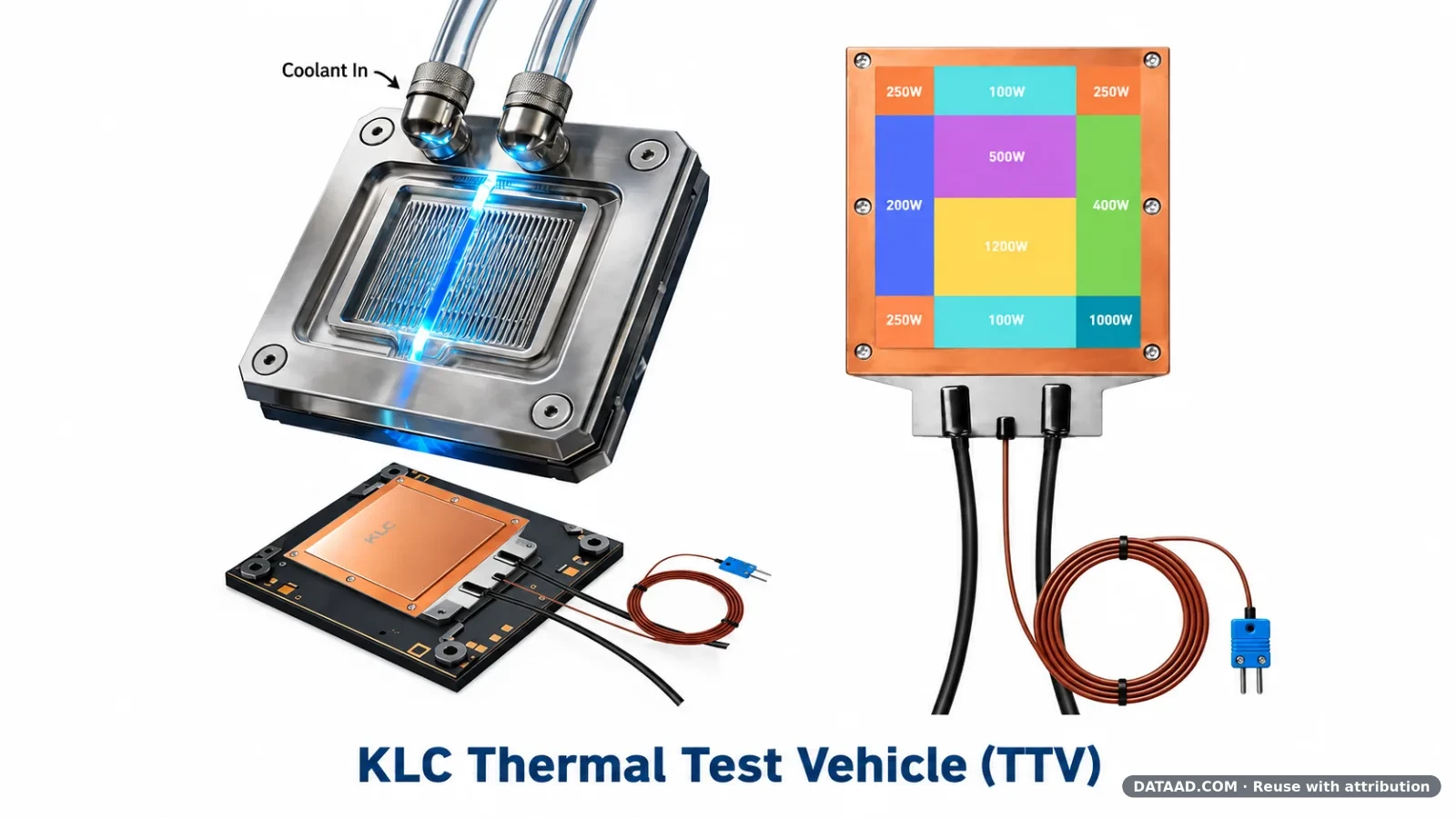
KLC's thermal test vehicle approach brings the heat source, temperature sensing and mechanical interface into one test specification. Its TTV 2.0 platform combines standardized heating modules with application-specific interfaces for AI processor and cold-plate development. Published measurements for a 50 × 50 mm TTV now provide a concrete example of how temperatures evolve along the heat-transfer path as electrical power increases. [1]
KLC specifies its standard products up to 5,000 W. Higher-power configurations can be developed for customer-specific requirements and operating conditions. The published sweep extending to 8,000 W is a test example, not an 8,000 W standard product rating or a guarantee that every configuration can operate at that power.

Figure 1. KLC TTV 2.0 product configurations. Official product composite supplied by KLC; the image is not a photograph of the reported test setup. Source: KLC Corporation.
Specify the Heat Source as Part of the Experiment
A thermal test vehicle supplies a defined heat load without requiring an operating processor for every experiment. Total input power alone does not describe that load. The heated footprint, spatial power distribution, sensor positions and contact with the cooling assembly all affect what the measurements mean. Two heaters drawing the same electrical power can therefore present different thermal challenges to a cold plate.
Read the Measured Temperatures Along the Heat Path
KLC's published 50 × 50 mm test charts report ambient and water temperatures of 27.2°C. Figure 2 plots TTV core, TTV surface, cold-plate and water-outlet temperatures against input power. These separate traces are more informative than a single headline temperature because they identify where each reading sits in the assembly. [1]
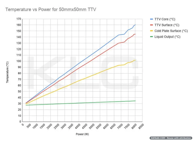
Figure 2. Supplier-reported temperature measurements for a 50 × 50 mm TTV. The sweep reaches 8,000 W under the reported test configuration; standard products remain specified up to 5,000 W. KLC lists ambient and water temperatures of 27.2°C. The curve is reproduced without redrawing or extrapolation. Source: KLC Corporation.
In this sweep, the core, surface and cold-plate temperatures rise with power, while the outlet-water temperature changes less. That is a configuration-specific observation, not a universal temperature prediction. The published material does not provide a complete reproducibility record: coolant flow, interface material, clamping load, stabilization time and measurement uncertainty are not established here. Those conditions are needed before comparing the curves with another laboratory's results.
Use Temperature Differences to Examine the Interface
Figure 3 separates the core-to-surface temperature difference from the surface-to-cold-plate difference. In the published sweep, the latter grows more strongly. This helps direct attention to the interface and measurement locations when planning further tests; it does not isolate the thermal resistance of any single material. [1]
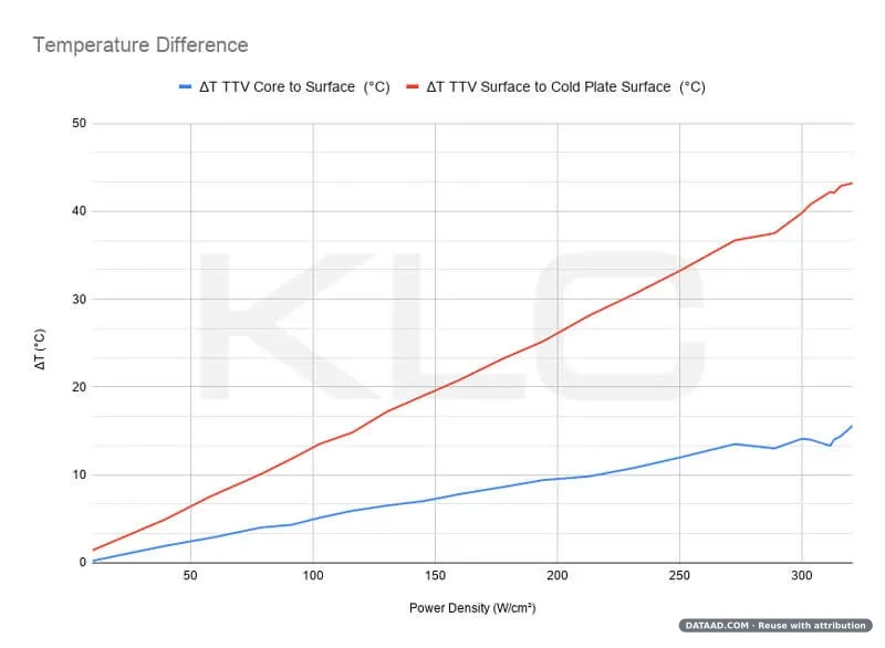
Figure 3. Supplier-reported temperature differences versus power density. The density axis describes this test presentation, not a general standard-product rating. Sensor locations and the complete test conditions must be matched before using these curves for quantitative comparisons. Source: KLC Corporation.
Match the Power Map to the Cooling Question
For spatially uneven loads, KLC offers customizable multi-zone configurations tailored to each customer's heating layout, power distribution and sensing requirements. Engineers can assign different powers to selected regions to investigate localized loads associated with chiplet or memory layouts. These options should be specified separately from a standard single-zone module; reproducing a selected power map does not reproduce every aspect of a functioning processor. [2]
A test can hold total power constant while changing its allocation among zones, separating the effect of spatial loading from the response to total input power.
Connect the Heater to a Defined Mechanical Interface
KLC combines standardized heating elements with customizable copper interfaces and precision-machined structures. TTV 2.0 incorporates T-type temperature sensing, while sensor arrangements and fixtures can be adapted to the application. KLC specifies surface roughness Ra below 0.4 µm; this is a roughness specification, not a flatness tolerance. Combining these elements makes the heater's physical fit and thermal contact part of the test design. The external power supply and controller remain part of the configured test system. [1]

Figure 4. KLC schematic of a thick-plate TTV clamped beneath a cold plate. Not to scale; this illustration does not establish the exact fixture or clamping load used for Figures 2 and 3. Source: KLC Corporation.
A useful test specification distinguishes active heating area from overall dimensions and records zone powers, sensor locations, interface material, mounting load, coolant inlet temperature and flow. Power-supply voltage and current limits also need to match the selected load. These inputs allow engineers to define a repeatable experiment before interpreting temperature changes as a cooling-design improvement.
TTV measurements can support cold-plate and thermal-interface development under selected conditions. They do not by themselves certify an accelerator, rack or complete AI system. The practical starting point is a documented heat-load map and interface specification, followed by measurements whose boundary conditions are explicit.
DATAAD Technical Analysis: Multi-Zone Thermal Testing Meets Two-Phase Matrix Flow Boiling
The following section is an independent technical analysis by DATAAD, examining a potential application of KLC's multi-zone thermal testing technology to advanced two-phase liquid cooling systems. It is not part of KLC's original contributed manuscript.
As AI processors become more complex, thermal management must address not only increasing total power consumption but also uneven heat generation across individual processing regions.
Advanced GPU packages, chiplets and memory interfaces can create localized concentrations of heat that challenge conventional methods of evaluating cold-plate performance.
This is where KLC's configurable multi-zone Thermal Test Vehicle technology becomes particularly relevant.
By applying different electrical power levels to selected heating regions, engineers can simulate spatially uneven heat loads while controlling the overall thermal input.
An emerging application for this testing approach is the evaluation of advanced two-phase direct liquid cooling technologies.
ZutaCore OmniTherm: Localized Heat Removal Through Matrix Flow Boiling
ZutaCore's OmniTherm technology introduces a Matrix Flow Boiling architecture designed around multiple localized boiling regions.
According to ZutaCore's technical presentation, each boiling region is independently supplied with coolant and provided with a vapor discharge path.
The architecture is intended to support efficient cooling under concentrated thermal loads and changing installation orientations.
ZutaCore reports a 600 W GPU cooling implementation, with a coolant flow rate of 0.4 L/min per card under its stated configuration.
The company also reports an approximately 8°C improvement relative to its earlier HyperCool technology. This is a manufacturer-reported comparison and should not be interpreted as independently verified performance across all operating conditions.
These developments create an interesting technical connection between KLC's controllable heat-generation platform and ZutaCore's localized two-phase heat-removal architecture.
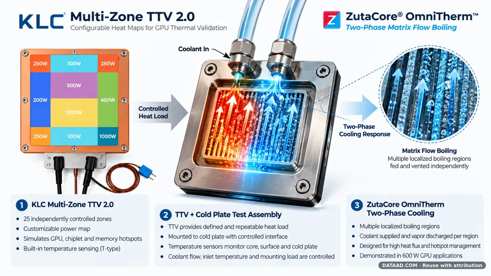
DATAAD Illustration 1. Conceptual connection between KLC Multi-Zone TTV 2.0 thermal testing and ZutaCore OmniTherm Two-Phase Matrix Flow Boiling. This illustration presents a proposed validation approach, not an actual joint test or verified product integration. Sources: KLC and ZutaCore product materials; DATAAD technical illustration.
Can a Multi-Zone TTV Evaluate Localized Two-Phase Cooling Performance?
A multi-zone Thermal Test Vehicle could provide a controlled heating platform for investigating how a two-phase cold plate responds to different spatial heat distributions.
For example, a cooling assembly could be tested under a uniform heating condition, followed by a concentrated hotspot condition with the same total electrical power.
Engineers could then compare maximum surface temperatures, temperature uniformity, transient response, coolant flow and pressure behavior under the two conditions.
Such testing would be especially relevant to cooling architectures designed to respond to localized thermal loads.
However, the individual heating regions of a TTV should not be assumed to correspond directly to the individual boiling regions within a cold plate.
Thermal spreading, contact resistance, internal cooling geometry and fluid behavior all influence the relationship between the applied heat distribution and the resulting cooling response.
Consequently, the test setup must be designed with carefully documented boundary conditions and appropriate temperature measurement locations.
A Proposed 600 W GPU Hotspot Validation Experiment
One possible experimental approach would use a configurable multi-zone TTV to simulate different heat distributions at a constant total electrical load of 600 W.
Test A: Uniform Heating
The total 600 W is distributed across the active heating area according to a defined uniform or near-uniform power map.
Engineers measure temperature distribution, maximum surface temperature and the response of the cooling assembly.
Test B: Localized Hotspot Heating
The same total 600 W is redistributed among selected heating regions to create one or more localized hotspots.
Temperatures and cooling system behavior are compared against the uniform heating condition.
Test C: Dynamic Hotspot Redistribution
Where the selected TTV configuration supports suitable dynamic power control, heat generation is shifted between different regions while total electrical power remains approximately constant.
This experiment could investigate the transient response of the cold plate to changing thermal conditions.
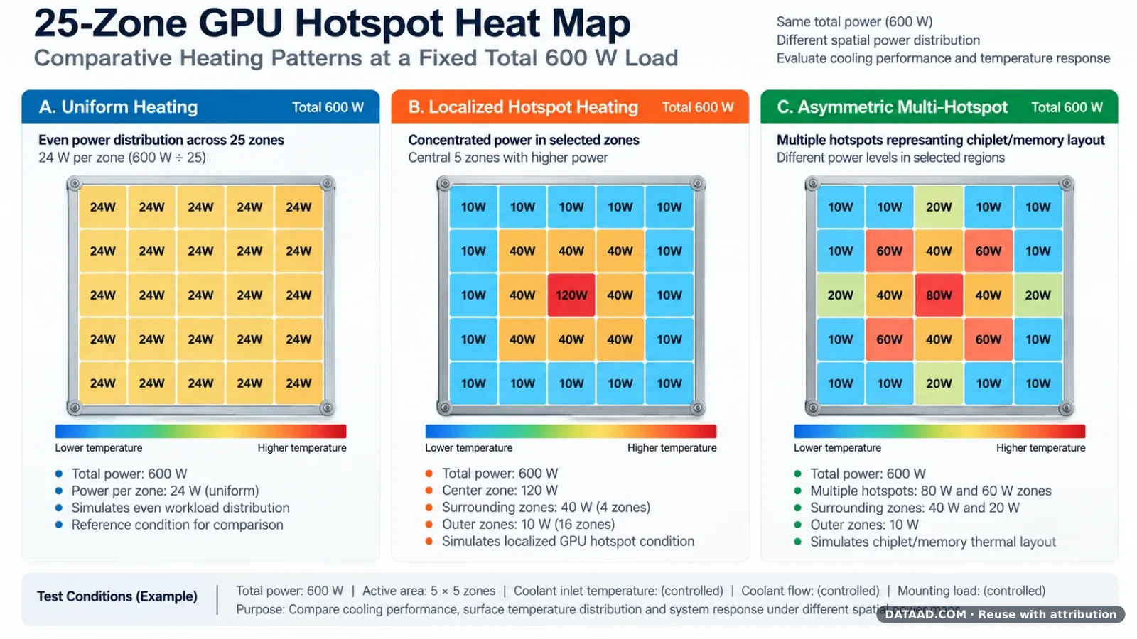
DATAAD Illustration 2. Conceptual 25-zone thermal heat map illustrating different localized heating patterns under a fixed total 600 W load. The diagram is illustrative and does not represent published experimental results or a completed KLC-ZutaCore validation test.
For meaningful results, coolant inlet temperature, coolant flow, system pressure, interface material, mounting conditions and measurement uncertainty should be recorded or controlled.
The dynamic characteristics of the heating device and temperature measurement system must also be appropriate for the transient phenomena being investigated.
Beyond Maximum Cooling Capacity
The broader significance of these testing methods extends beyond the evaluation of any single cold plate or cooling technology.
As AI infrastructure adopts higher-density computing, engineers increasingly need reproducible methods for assessing the response of cooling systems to complex thermal conditions.
Maximum rated cooling power alone cannot fully describe the thermal performance of a system operating under localized or rapidly changing heat loads.
Configurable multi-zone Thermal Test Vehicles offer a way to examine these conditions systematically, while emerging two-phase cooling technologies introduce additional questions about localized boiling, vapor removal and transient thermal stability.
The combination represents a promising area for future engineering investigation, provided that actual hardware compatibility and experimental conditions are independently established.
DATAAD Perspective
The next generation of AI infrastructure will require closer cooperation between semiconductor developers, thermal testing specialists and liquid cooling system manufacturers.
Rather than evaluating thermal performance solely by headline wattage, the industry should increasingly examine how heat is distributed across the processor package and how effectively it can be removed under realistic operating conditions.
KLC's TTV 2.0 technology provides a practical example of how configurable heat sources can contribute to this process.
Technologies such as ZutaCore's OmniTherm also demonstrate why localized heat removal is becoming an important consideration in advanced AI cooling design.
The potential relationship between these technologies remains a proposed application rather than a demonstrated joint development.
Nevertheless, the underlying engineering question is increasingly relevant:
The future of AI cooling is not simply about removing more heat. It is about understanding where heat is generated and validating how effectively it can be removed.
About KLC
KLC provides electric heating and thermal test vehicle solutions, drawing on more than 40 years of heating-engineering experience. Its portfolio includes standard and customized configurations.
Product and engineering contact: info@ptc-heater.com.tw
Product information: KLC Thermal Test Vehicle (TTV)
Contributor
Joanna Wu
KLC Corporation, Taiwan
Joanna Wu has more than 20 years of experience in PTC thermal solutions and electronics design. Her background includes advanced product development, testing and EV battery thermal management projects.
Sources and Product Information
[1] KLC TTV 2.0 Product Information and Published Test Charts
[2] KLC Corporation, Multi-Zone Thermal Test Vehicle technical information.
[3] ZutaCore, OmniTherm Two-Phase Matrix Flow Boiling technical presentation and manufacturer materials.
Editorial Disclosure
This article combines technical material contributed by KLC Corporation with additional technical analysis prepared by DATAAD.
The author is affiliated with KLC Corporation. The published thermal measurements are supplier-reported and have not been independently verified by DATAAD.
The analysis concerning ZutaCore OmniTherm is a proposed engineering application and does not imply that KLC and ZutaCore have conducted joint testing, established product compatibility or entered into a commercial relationship.